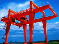
Bridge Crane Design Calculation
Bridge Crane Design Calculation
Bridge Crane for Foundry 130/30t-22.5m A8 Design Calculation
I. The outline of Design Calculation
The thread as follows:
Hook parameter is determined based on the rated lifting capacity;
According to the dead load of hook and max lifting height from rated lifting capacity to determine the motor model, pulley diameter, rope diameter, roll diameter, wall thickness, reducer Model and brake models;
According to user’s requirements on hook limit position to determine the layout of the trolley;
Estimate the trolley dead load and maximum wheel load to determine the number of trolley wheels and wheel diameter, and with the rated lifting capacity to determine the main beam section size;
Estimate the total weight of the crane, and estimates crane maximum wheel according to lift and right limit position of hook;
To determine the diameter of wheel, checking the trolley running motor power, and determine the reducer and brake model according to maximum wheel pressure;
Determine the size of the key components of the crane balanced arm and axle;
II. General Requirement and Known Parameters of the crane
Capacity: Main Hoist Q1=130000kg
Aux. Hoist Q2=30000kg
Span:19m
Lifting Speed: Main Hoist VMH=0.46~4.6m/min
Aux. Hoist VAH=1.2~12m/min
Cross Travel:VCT=1.91~19.1m/min
Long Travel: VLT=7.8~78 m/min
Lifting Height: Main Hoist 20.5m,Aux. Hoist 22.5m
Max. wheel load:≤595Kn
Max. Height of the crane:4400mm
Max. Width of the crane:14300mm
Hook Approaches: Aux Hoist Cabin end 1550mm
Main Hoist Opp. End 2300mm
Crane Work Duty:A8 Mechanism Work Duty:M8
Unit as follows if no specified in the design calculation:
Force, Weight: N,Kg
Length: mm
Time: min
Stress: MPa
Moment (Torque):N.m
Ⅲ. Calculation content and procedures
1 Calculation:
1.1 Cabin follow the original series, considered as independent components in the machine, so it is not regarded in this design calculation manual.
1.2 Walking platform and railings are all made in accordance with the relevant national standards, ministerial standard, so it is not regarded in this design calculation.
1.3 Gear Couplings provided by qualified subcontractor with long-term cooperation, so it is not regarded in this design calculation.
2、Calculation Process and The Results:
2.1 Main Hoist Mechanism
2.1.1 Motor Selection:
Static Power:
Nj=(QH+G0)×V/102/60/m/η
Where:
QH --Capacity=130000Kg
G0—Hook Weight=14000Kg
V—Lifting Speed=4.6m/min
η-- Gross Efficiency=0.85
m—No.s of motors
Nj=63.67Kw
Calculation Power:
Ne=Kd×Nj
Where:
Kd-- coefficient=1.1
Ne=70.03Kw
Primary motor:QABP315S6A,2×75Kw。
b、Motor overload checkout
Motor power rating when benchmark duty PN≥H×Nj /λT
H:coefficient,H=2.2
λT:when benchmark cyclic duration factor, allowed motor overload multiple,λT=3.0
=H×Nj/λT=51.36kw
Single motor QABP315S6A power rating when benchmark duty is 75kw。
So motor QABP315S6A meets the requirements.
2.1.2 Wire rope calculation:
Capacity QH=130t
Work duty :M8
Pulley Ratio m=2×4
Factor of Safety n=9
Pulley Efficiency η=0.97
Wire rope Calculation tension :
Smax= QH×9.81×1000/2/m/η/2=92.84kN
Allowed breaking force of wire rope:
S=n×Smax=835.56kN
Wire rope selected: 36NAT-6×36WS+IWR1870,its nominal tension 863[KN],is greater than Max. breaking force. So 30NAT-6×19WS+IWR1870 meets the requirement。
Then we can get Groove pitch of drum t=40mm。
2.1.3 Drum parameter calculation, Strength calculation and stability calculation.
Calculation results :
(1)Structure of drum
Dia. Of wire rope d=36 mm
Dia. Of drum D= 800 mm
The standard of groove shape: International standard.
Groove Pitch p= 40 mm
The length of drum with groove L0:
L0 =H*m/π/D0*p+z1*p
Where:
H—Lifting height=20.5m
m— Pulley Ratio =4
D0— Calculation dia. of drum =D+d=836 mm
z1—Safety loop: 3
L0 = 1368.87 mm
Number of groove(inclusive safety loop)=34.22
Total length of drum L:
L =2*(L0+L1+L2)+Lg
Where:
L1-- front end length=p=111 mm
L2—length of groove for fixing wire rope=3p=102 mm
Lg—length of middle drum without groove=100 mm
L = 3263.74 mm
Set L=3300mm
Drum plate thickness and checkout:
Plate thickness t=22 mm
Material:Q345B
Yield strength of the material:σs=325 MPa
(2) Pressure stress of drum checkout:
Pressure stress of drum plateσ1=106.98 MPa
Safety factor of the drum strength n=σs/σ1=3.04
For safety factor of plate, n should be greater than or equal to 2.
*So, meet the requirement.*
(3) Drum stability checkout:
When dia. of drum D>1200mm,or length of drum L>2D,we should check drum stability.
P=5.8MPa
Stability unit pressure stress of drum plate P0=18.49 MPa
Stability coefficient k= P0 /P=3.19
For safety factor of plate n should be greater than or equal to 1.3.
* So, meet the requirement. *
2.1.4 Selecting calculation of gearbox and brake
Selection of hoist gearbox:
Rotating speed of drum:
nj=V×bi/π/D0
Where:
V—Lifting speed=4.6m/min
bi—Pulley ratio=4
D0—Effective dia. of drum
D0=dia. of drum +dia. of wire rope=0.836m
nj=7.01r/min
Computing torque of drum:
T=(Q+G0)/bi×D0/2×1.1
In the caculation:
Q—Capacity =130000Kg
G0—Hook weight=14000Kg
T=165528N.m
Calculation Power of gearbox:
Nj= 2xNe= 140.07Kw
Gear ratio of gearbox:
i=nd/nj
Where:
nd- Rotating speed of motor=990r/min
i=141.23
Actual lifting speed:
V'=V×i0/i0'=4.64
Where:
V—Lifting speed=4.6m/min
i0-Calculation ratio=141.23
i0'-Actual ratio=140
Gearbox is non-standard designed ,Ratio designed 140,Allowed input power designed of high-speed shaft of gearbox should be greater or equal to 140 kW。
a、 Selection of brake
The plan is: 4 brakes mounted on the double side input pinion shaft of the gearbox.
The minimum braking Torque of unit brake:
Mz=Kz×(Q+G0)×D0/2/bi/i×η=1316.7N.m
Where:
Kz—Safety factor of braking=1.25
bi—Pulley ratio=4
D0—Actual dia. of drum 0.836m
D0=(Dia. of drum +Dia. of wire rope)
η=Transmission efficiency of the mechanism =0.98
According to the brake catalogue YWZ9-500/E121S is selected,The rating braking torque M=2500N.m> Mz,So the brake meets requirement.
2.2 Aux. Hoist Mechanism
Calculation method and process are same to main hoist mechanism. Ignore the process,results as follows:
Motor:QABP315S6A
Gearbox:QY3D400-45
Brake:YWZ9-400/E80(double)
Wire rope:20NAT-6×19W+IWR1870
Dia. of drum:Φ650mm
Pulley ratio:4
2.3 Cross travelling mechanism
The plan is: 4 wheels, two active wheels are driven by two mechanisms via coupling. Dia. of trolley wheel dCT=700mm。
2.3.1 Selection of motor
Friction torque:
Mm=(Q+Gxc)(k+μ×d/2)β=10197N.m
Wherer:
Q --Capacity=130000Kg
Gxc-Trolley weight=76000Kg
k - Coefficient of rolling friction=0.0008
μ- Bearing friction coefficient=0.02
d - Bearing bore diameter=0.1675m
β- additional resistance coefficient=2
Travelling friction resistance:
Pm=2×Mm/Dc=29134.29N.m
Where:
Dc –Dia. of wheel=0.7m
Motor static power:
Nj=Pm×Vxc/1000/60/η/m=5.15Kw
Where:
Vxc –Speed of cross travel=19.1m/min
η- Transmission efficiency of the mechanism =0.9
m-Number of driven motors=2 sets
Motor power:
N=kd×Nj=7.21Kw
Where:
kd - Increase coefficient of power=1.4
Motor selection:QABP160M6A,Ne=7.5Kw
2.3.2 Selecting calculation of gearbox
Rotating speed of wheel :
nc=Vc/π/Dc=8.69r/min
Where:
Vc—Traveling speed=19.1m/min
Dc—Dia. of wheel =0.7m
Gear ratio of gearbox:
i0=nd/nc=112.2
Where:
nd-Rotating speed of motor=975r/min
Actual travelling speed:
V'=Vc×i0/i0'=19.13m/min
Where:
i0-- Calculation ratio=112.2
i0'-- Actual ratio=112
According to the gearbox catalogue QY4S250L-112 is selected. Allowed input power of high-speed shaft of the gearbox for M7-duty P=12.8kw > N=7.21kw,so meet the requirement。
2.4 Long travelling mechanism
The plan is: 4 corner drive, motors, gearboxes and brakes be set inside of main girder, low speed shaft of gearbox be connected with wheels via universal coupling.
Calculation method and process are same to cross travelling mechanism. Ignore the process,results as follows:
Motor:QABP200L6B
Gearbox:QY3D250-31.5
Brake:YWZ4-300/E50
Dia. of wheel:800mm
Bearing bore diameter of LT wheel:210mm
2.5 Bridge
2.5.1 Calculation of main girder
Calculating load and parameter of main girder as follow:
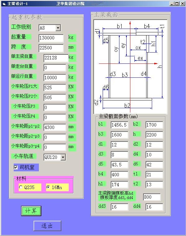
b1= 1456.5 mm, b2= 1700 mm
b3= 1600 mm, d1= 12 mm
d2= 12 mm, d3= 8 mm
d4= 10 mm, d5= 43.5 mm
d6= 42 mm, h= 2200 mm
b4= 400 mm,t1= 21 mm
h1= 174 mm, t2= 13 mm
Height and thickness of web plate of girder end:
hd= 800 mm
dd3= 16 mm, dd4= 16 mm
Area:
s1= 86400 mm^2
ox= 700.12 mm, oy= 1023.32 mm
Flexural center:
ex= 710.11 mm, ey= 1100 mm
Moment of inertia:
ix= 72694407470 mm^4
iy= 38953130734 mm^4
Section modulus in bending:
(Point upright):
wx1= 69609321.82 mm^3
wy1= 42965223.52 mm^3
(Point lower right):
wx2= 61155574.18 mm^3
wy2= 51929199.31 mm^3
(Point upleft):
wx3= 70214433.18 mm^3
wy3= 41008475.32 mm^3
(Point lower left):
wx4= 61155574.18 mm^3
wy4= 41008475.32 mm^3
Static moment of inertia to neutral axis:
(Part of upright)
sx1= 17564468.51 mm^3
(Part of up left)
sx2= 14799303.49 mm^3
(Part of lower right)
sx3= 17568701.95 mm^3
(Part of lower left)
sx4= 15921501.27 mm^3
2. Girder end section features
Area:
s1= 71356 mm^2
Centroid:
ox2= 746.03 mm, oy2= 370.59 mm
Moment of inertia:
ix2= 8911070379 mm^4
iy2= 29925917434 mm^4
Static moment of inertia to neutral axis:
(Part of upright)
ssx1= 4920178.21 mm^3
(Point upleft)
ssx2= 4402393.79 mm^3
(Point lower right)
ssx3= 5592537.51 mm^3
(Part of lower left)
ssx4= 5219960.78 mm^3
3. Design load of girder
Bending moment due to self-weight of girder:
m1=qzl*l*l/8= 622350000 N.mm
Bending moment due to self-weight of plateform:
m2=qzt*l*l/8= 0 N.mm
Bending moment due to wheel load:
m3= 4708000000 N.mm
Bending moment due to drive mechanism:
m4= 250000000 N.mm
Bending moment due to the load of cabin:
m5= 9000000 N.mm
Total vertical bending moment:
mz=m1+m2+m3+m4+m5= 5589350000 N.mm
Horizontal bending moment due to inertial load:
mg= 558935000 N.mm
4. Stress of middle section in girder
Normal stress of point (1):
σ1= 93.31 Mpa
Normal stress of point (2):
σ2= 102.16 Mpa
Normal stress of point (3):
σ3= 93.23 Mpa
Normal stress of point (4):
σ4= 105.03 Mpa
Normal stress of point (5):
σ5= 103.55 Mpa < 1.4[σ]1
[σ]1--- Fatigue allowable stress
[σ]1=140 Mpa ( Q235 )
[σ]1= 210 Mpa ( 16Mn )
5. Point shear stress of web plate in middle girder
Point shear force of web plate in middle girder:
Qz= 708743.33 N
Shear stress of point (6):
τ6= 17.12 Mpa
Shear stress of point (7):
τ7= 18.04 Mpa
6. Point shear stress of web plate in end girder
Point shear force of web plate in end girder:
Qd= 1167306.67 N
Shear stress of point (8):
τ8= 36.04 Mpa
Shear stress of point (9):
τ9= 40.28 Mpa
7. Vertical static rigidity of main girder
f= 15.19 mm < L/ 1000 = 22.5 mm
********************
* meet requirement *
********************
2.5.2 End beam intensity calculation:
This crane adopts four corners driving, the supporting point is in the end of the main beam, so the end beams substantially only affected by the crane lateral skew couple formed by the load in the actual work, and since by the main beam end portion constraints, end beams often taken and the same cross-section of the cross-section of the main beam ends in the production, the cross-sectional size is large, so the end beam is not regarded in this calculation book.
Ⅳ. Conclusion
According to the above calculation instructions:
1.The initial parameters meet the crane requirements.
2. The structural design of this crane is reliable and able to meet the requirements of the customer on rated lifting capacity, speed, and working life.
3. Design of this crane according with the “design specifications requirements of GB3811-2008”.
Ⅴ. Main References
1.“Crane Design Manual”, China Railway Press
2.“The metal structure” edited by Xu Kening, Machinery Industry Press
3.“Mechanical Design Handbook”, edited by Cheng Daxian, Chemical Industry Press
4.“Mechanics of Materials”, edited by Liu Wenhong, Higher Education Press
Weihua Crane is professional material handling equipment manufacturer and servicer with largest production in global. Provide you with overhead crane, gantry crane, electric hoist, etc. of safe, reliable and efficient crane solutions and services.
Contact Us
Simply complete the form below, click submit, you will get the price list and wo will contact you within one business day. Please also feel free to contact us by email or phone.
Recommend
Contact Us
Industry Park, Changyuan, Henan, P.R.C
 marketing@craneus.com
 contact@craneus.com
- Tel:(0086) 15836006986
- Fax:(0086) 373 8883166
- Skype:wei.crane

